NDM2Z-630
271. Applicable Scope and Purpose of Circuit Breaker The NDM2Z-630 DC molded case circuit breaker (hereinafter referred to as circuit breaker) applies to the DC system application e...
View details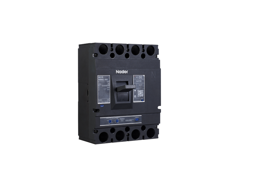
1. Applicable Scope and Purpose of Circuit Breaker
The NDM2L-400 molded case circuit breaker with the residual current protection (hereinafter referred to as circuit breaker) applies to infrequent switching of circuits with the AC 50/60Hz, the working voltage of AC415V and the working current up to 400A. With the overload, short circuit and undervoltage protection functions, the circuit breaker can protect lines and power equipment from damage. Meanwhile, they can deal with the personal safety, fire hazards and other potential risks caused due to long-term ground faults that can’t be detected with the overcurrent protection function.
2. Specification and Model Description of CircuitBreaker
| ND M 2 L – □ □ □ / □ □ □ / □ □ □ □ □ □ □1 2 3 4 5 6 7 8 9 10 11 12 13 14 15 16 17 | ||
| SN | SN name | NDM2L |
| 1 | Enterprise code | ND: “Nader” low-voltage apparatus |
| 2 | Product code | M: Molded case circuit breaker (MCCB) |
| 3 | Design SN | 2 |
| 4 | Derived code of the | L: Residual current protection |
| 5 | Shell frame level | 400 |
| 6 | Breaking capacity level | M: Relatively high breaking type |
| H: High breaking type | ||
| 7 | Operation mode | No code: Direct handle-operated mode |
| P: Motor-operated | ||
| Z: Rotary operation | ||
| 8 | Derived code of the function | No code: Type AC current leakage protection type |
| A: Type A current leakage protection type | ||
| 9 | Delay type | X: Non-time delay |
| Y: Delay | ||
| XI: Non-time delay + alarm non-tripping | ||
| YI: Delay + alarm non-tripping | ||
| 10 | Residual current release | V: Type V residual current release |
| 11 | Number of poles | 3, 4 |
| 12 | Release code | 3: Complex tripper |
| 13 | Accessory code | See Table 1 |
| 14 | Application code | No code: Power distribution type |
| 15 | N-pole (neutral pole) type of the 4P product | A: The N-pole isn’t installed with an overcurrent release, but always |
| B: The N-pole isn’t installed with an overcurrent release, but on-off | ||
| C: The N-pole is installed with an overcurrent tripper, and on-off with | ||
| 16 | Rated current | See Table 2 |
| 17 | Cabling type | No code: Normal product |
| P: Connection busbar | ||
| Z1: Rear-plate connection | ||
| Z2H: Plug-in rear-plate connection | ||
| Z2Q: Plug-in front-plate connection | ||
| Z3H: Integrated plug-in rear-plate connection | ||
| Z3Q: Integrated plug-in front-plate connection |
3. Main Technical Parameters of Circuit Breaker
Table 2 Main Technical Parameters of Circuit Breaker
| Model | NDM2L-400 | |||||||
| Rated current of frame Inm (A) | 400 | |||||||
| Rated current In (A) | 225, 250, 315, 350, 400 | |||||||
| Rated insulation voltage Ui (AC V) | 1000 | |||||||
| Rated impulse withstand voltage Uimp (V) | 8000 | |||||||
| Rated working voltage Ue (AC V) | 380/400/415 | |||||||
| Utilization category | A | |||||||
| Number of poles | 3 | 4 | ||||||
| Breaking capacity level | M | H | / | |||||
| Rated limit short-circuit breaking capacity Icu (kA) | 65 | 100 | 65 | |||||
| Rated operating short-circuit breaking capacity Ics (kA) | 42 | 70 | 42 | |||||
| Rated residual short-circuit making and breaking capacity I△m(kA) | 0.25 Icu | |||||||
| Rated residual action current I△n(mA) | Non-time delay | Type AC | Type V 30/300/500/1000 | |||||
| Type A | Type V 30/300/500/1000 | |||||||
| delay | Type AC | Type V 300/500/1000 | ||||||
| Type A | Type V 300/500/1000 | |||||||
| Rated residual non-action current I△no(mA) | 0.5I△n | |||||||
| Residu al current actiontime | Residual current | I△n | 2I△n | 5I△n | 10I△n | |||
| Non-time delay | Maximum breaking time (s) | 0.2 | 0.1 | 0.04 | 0.04 | |||
| delay | Maximum breaking time (s) | 0.5, 1.152.15 | 0.35, 12 | 0.25, 0.91.9 | 0.25, 0.91.9 | |||
| Limit non-driving time (s) | / | 0.1, 0.51 | / | / | ||||
| Operating performance (times) | Electrical life | 7500 | ||||||
| Mechanica l life | Maintainable free life | 10000 | ||||||
| Maintainable life | 20000 | |||||||
3.1Selection of the circuit breaker connecting bus or cable cross-section area:
Table 3 Selection of the NDM2L-400 Connecting Bus or Cable Cross-section Area
| Rated current (A) | 225 | 250 | 315, 350 | 400 |
| Wire cross-section area (mm2) | 95 | 120 | 185 | 240 |
3.2Tightening Torque of the Circuit Breaker Terminal and Mounting Screw
Table 4 Tightening Torque of the Circuit Breaker Terminal and Mounting Screw
| Model | Thread diameter (mm) | Torque (N·m) |
| NDM2L-400 | M10 | 20 |
| M6 | 6 |
3.3Derating factor of temperature change for the circuit breaker
Table 5 Derating Factor Table of Temperature Change for the Circuit Breaker
| Model | Derating factor of product temperature change | |||||||
| NDM2L-400 | Temperat ure (℃) | 40 | 45 | 50 | 55 | 60 | 65 | 70 |
| Derating factor | 1 | 0.981 | 0.962 | 0.942 | 0.922 | 0.901 | 0.879 | |
3.4High-altitude derating factor of the circuit breaker
Table 6 High-altitude Derating Factor Table of Circuit Breaker
| Elevation (m) | Working current correction coefficient | Power frequency withstand voltage correction coefficient | Isolation voltage correction coefficient(V) |
| 2000 | 1 | 3500 | 1000 |
| 2500 | 1 | 3500 | 1000 |
| 3000 | 0.98 | 3150 | 900 |
| 3500 | 0.97 | 3000 | 850 |
| 4000 | 0.95 | 2800 | 810 |
| 4500 | 0.94 | 2650 | 770 |
| 5000 | 0.93 | 2500 | 730 |
5.Outline and Mounting Hole Dimensions of Circuit Breaker
5.1Outline and mounting hole dimensions of circuit breaker
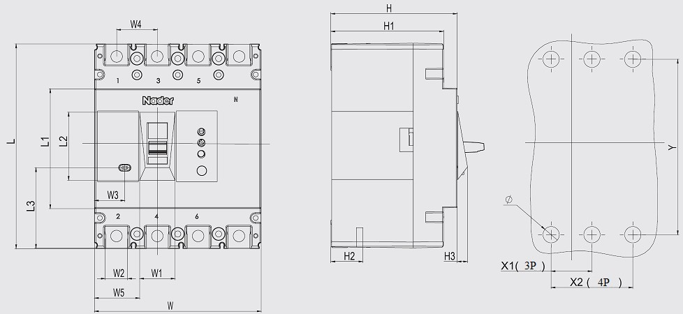

Note: The limit deviation not indicated with the tolerance dimensions is as per GB/T 1804-c.
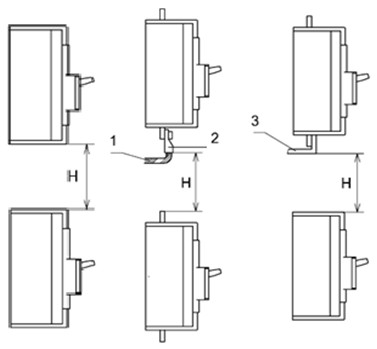
5.2Safe mounting distance of circuit breaker
Table 7 Insulation Distance Mounted in the Metal Cabinet (Unit: mm)
| Mounting distance | A (inlet wire end to the cabinet face) | B (distance from side to the cabinet face) | C (outlet wire end to the cabinet face) | |
| Model | With a terminal cover | Without a terminal cover | ||
| NDM2L-400 | 25 | 120 | 35 | 35 |
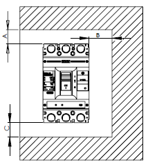
Table 8 Minimum Center Distance between Rowed Circuit Breakers (Unit: mm)
| Model | Width of circuit breaker | I Center distance | ||
| 3 poles | 4 poles | 3 poles | 4 poles | |
| NDM2L-400 | 150 | 198 | 190 | 238 |
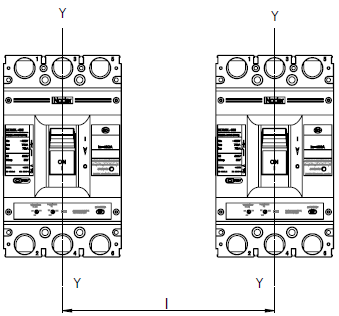
Table 9 Minimum Distance between Stacked Circuit Breakers (Unit: mm)
| Model | H (distance of circuit breaker from bottom) | |
| With a terminal cover | Without a terminal cover | |
| NDM2L-400 | 155 | 155 |
Requirements: Check whether the terminal cover or phase partition is assembled properly before products are energized.
1. Applicable Scope and Purpose of Circuit Breaker The NDM2Z-630 DC molded case circuit breaker (hereinafter referred to as circuit breaker) applies to the DC system application e...
View details1.Applicable Scope and Purpose of Circuit BreakerThe NDM2L-400 molded case circuit breaker with the residual current protection (hereinafter referred to as circuit breaker) applies to infreque...
View details1. Applicable Scope and Purpose of Circuit Breaker The NDM2Z-250 DC molded case circuit breaker (hereinafter referred to as circuit breaker) applies to the DC system application environment...
View details1.Applicable Scope and Purpose of Circuit BreakerThe NDM2L-630 molded case circuit breaker with the residual current protection (hereinafter referred to as circuit breaker) applies to infreque...
View details
HelloPlease log in